- All
- Product Name
- Product Keyword
- Product Model
- Product Summary
- Product Description
- Multi Field Search

Views: 19 Author: Xicheng EP Ltd Publish Time: 2022-07-25 Origin: Xicheng EP Ltd
The types of waste gas generated during workshop production include particulate matter, S02, Nox, and VOCs. According to the type of waste gas produced, one is nitrogen oxides and the other is total volatile organic compounds, which are divided into two processes for treatment:
1. The oily exhaust gas is sucked into the electrostatic fume purifier by the fan, and some of the larger oil mist droplets and oily particles are captured on the equalizing plate due to mechanical collision and retention. When the airflow enters the high-voltage electrostatic field, under the action of the high-voltage electric field, the oil fume gas is ionized, the oil mist is charged, and most of them are degraded and carbonized; a small number of tiny oil particles are attracted to the positive and negative of the electric field under the action of the electric field force of the adsorption electric field and the airflow. The movement of the plate is collected on the plate and flows to the oil storage tank under the action of its own gravity. At the same time, under the action of the high-voltage generator, the air in the electric field produces ozone, which removes most of the odor in the flue gas. The treated oily waste gas enters the UV photolysis purifier together with the VOC waste gas. The UV photolysis purifier uses different UV light in each section to crack it, and the air generates ozone under the irradiation of UV light to further oxidize and decompose the waste gas, and then After the activated carbon adsorber, it is fully contacted with activated carbon, and the processes of gas dust adsorption and capture, deodorization, and oxidation are carried out.
2. The acid mist exhaust gas is introduced into the acid mist spray tower through the air duct, and passes through the swirl plate and the packing layer. After defogging by the defogging layer, it is discharged into the atmosphere by the fan.

This equipment mainly achieves the purpose of purification through the following three stages:
Flow equalization section: The fume flow is introduced through the air inlet, and is evenly distributed to the pretreatment section and the electric field section in the flow equalization section, ensuring the smooth flow of the fume flow.
Pretreatment: The pretreatment section adopts a multi-mesh stainless steel wire mesh. Has a strong fume adsorption capacity. In this process, most of the particles in the air flow are adsorbed and filtered due to the collision of the inertial effect with the pretreatment screen, which greatly reduces the concentration of oil mist particles after flowing out of the pretreatment section. At the same time, the pretreatment section has the characteristics of automatic oil draining and does not block, so that impurities can be trapped in the pretreatment section, and it has a certain fireproof function, thus ensuring the normal operation of the electric field.
High-voltage electrostatic section: After pretreatment, the concentration of soot is significantly reduced. The small particle oil mist droplets, oil and gas, and organic matter in the oil mist are ionized, decomposed, adsorbed and carbonized in the high-strength high-voltage electrostatic field, so the equipment has extremely high oil mist removal efficiency.
After long-term research, it has been found that when chemical substances absorb energy (such as heat energy, photon energy, etc.), their chemical properties can become more active or even cracked. When the absorbed energy is greater than the bond energy of the chemical bond, the chemical bond can be broken to form free atoms or groups with energy. By providing vacuum ultraviolet rays in the UV catalysis-D band (wavelength range 170-184.9nm), we promote organic waste gas substances to absorb photons in this band, and the photon energy in this band is greater than most of the chemical bond energy, making organic substances It can be cracked; then it is oxidized into simple, harmless and stable substances by the ozone generated by cracking, such as H2O and CO2.
Because the same as the combustion nature of organic waste gas, the energy absorbed by molecules (heat energy absorbed by combustion, photon energy absorbed by photolysis) is cracked and oxidized to form simple substances, and the reaction temperature of photolysis is normal temperature, so we are also used to Call it "cold burn".
By using vacuum ultraviolet rays in the UV-D band (wavelength range 170-184.9nm), the chemical bonds of organic waste gas molecules are destroyed, and they are cleaved to form free atoms or groups (C*, H*, O*, etc.); at the same time By cracking the oxygen in the mixed air, it forms free oxygen atoms and combines to generate ozone [UV catalysis +O2→O-+O*(active oxygen) O+O2→O3 (ozone)]. Ozone (O3), which has strong oxidizing properties, undergoes oxidation reaction with the atoms generated by the cracking of organic waste gas molecules to form H2O and CO2. The entire reaction process does not exceed 0.1 seconds, and the purification effect is related to the bond energy of the exhaust gas molecules, the exhaust gas concentration and the oxygen content. The entire purification process does not require any chemical additives or special restrictions.

Eg: The mechanism of photolysis and oxidation of benzene molecule![]()
Brief description of the principle of UV catalytic photolysis: Under the action of high-energy ultraviolet rays in the wavelength range of 170nm-184.9nm (704 kj/mol - 647 kj/mol), on the one hand, oxygen in the air is cracked, and then combined to produce ozone (see reaction ①, ②); on the other hand, the chemical bonds of the odorous gas are broken to form free atoms or groups (see reaction ③); at the same time, the generated ozone participates in the reaction process, so that the odorous gas is finally cracked and oxidized to form a simple stable compounds, such as SO2, H2O, etc. (see reaction ④).
It can be seen from the above molecular formula that high-energy ultraviolet light can split high-molecular-weight odorous chemicals into independent, free pollutant atoms, and then decompose oxygen in the air to generate active positive and negative oxygen ions, and then generate ozone. At the same time, the pollutant atoms that are cracked into independent and free states are re-polymerized into low-molecular compounds such as water, carbon dioxide, etc. through the oxidation reaction of ozone.
The theoretical basis of this principle is that the energy of the photons generated by the high-energy ultraviolet rays emitted by the high-energy ultraviolet lamp tube must be greater than the molecular bonding energy of the malodorous gas molecules, so that the malodorous gas molecules can be cracked, and the ozone generated by the cracking can be oxidized at the same time. Regenerates pollution-free H2O and CO2.
For example, the main components of pollutants in spray paint exhaust gas are benzene, toluene and xylene, and their molecular formulas are as follows: ![]()
![]()
![]()
As can be seen from the above figure, the chemical bonds contained in benzene, toluene and xylene molecules include C-C bonds, C=C bonds and C-H bonds. The following table lists common chemical bonds in organics and their bond energy parameters: The binding energy of some chemical molecular bonds in this table
binding | BE (KJ/mol) | binding | BE (KJ/mol) |
H-H | 436 | C-H | 413 |
C-C | 332 | C-F | 485 |
C=C | 611 | C-N | 305 |
C≡C | 837 | C≡N | 891 |
S-H | 339 | C-O | 326 |
S-S | 268 | C=O(CO2) | 728(803) |
O=O | 498 | O-H | 464 |
The table contains almost all chemical bond length and bond energy parameters of benzene, toluene, xylene, etc., and most of these bond energies are lower than the maximum UV photon energy (704kJ/mol) of the UV high-efficiency photolysis equipment. Therefore, in theory, the above compounds can be cleaved. It is not enough for waste gas molecules to be split into atoms and free radicals. It is also necessary to oxidize them into stable small molecules, such as CO2, H2O, etc. by ozone, so as to achieve the purpose of waste gas purification. Therefore, sufficient oxygen is required to be irradiated by high-energy UV catalytic light to generate ozone.
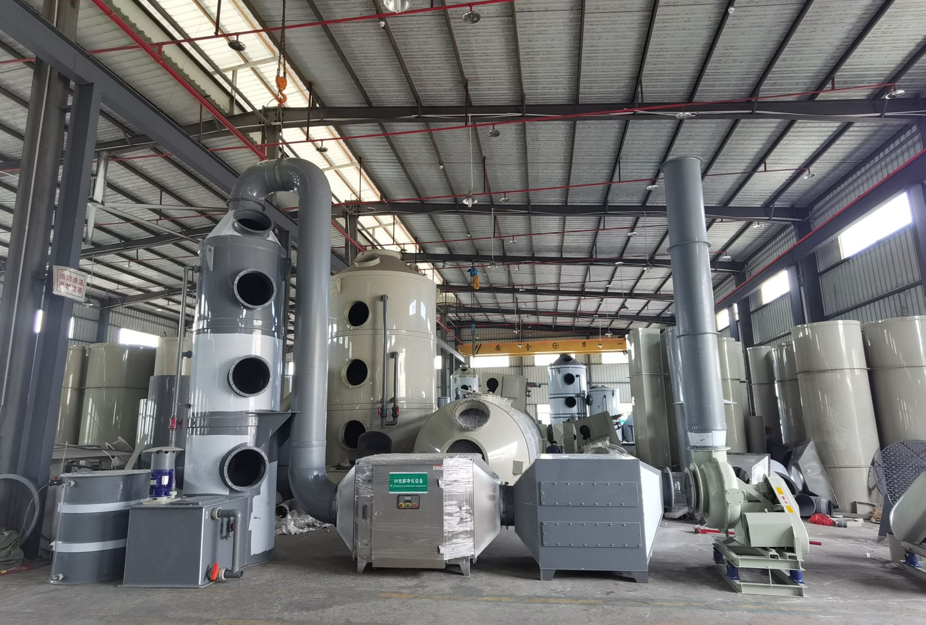
Activated carbon adsorber
The activated carbon adsorber is mainly used in the treatment of organic waste gas. The main body of the device is made of galvanized sheet, which has the advantages of power saving, convenient operation and maintenance, and high waste gas removal rate.
After the organic waste gas is collected, it enters the activated carbon adsorber under the action of the negative pressure of the fan. Activated carbon adsorption is developed by utilizing the porosity of activated carbon and the principle of attractiveness. Due to the existence of non-equilibrium saturated molecules or chemical bond forces on the solid surface, when the solid surface is in contact with the gas, the gas molecules can be attracted, concentrated and kept on the solid surface. This phenomenon is called adsorption. The activated carbon adsorption method used in this process utilizes this property of the solid surface. When the exhaust gas is in contact with the porous activated carbon with a large surface area, the pollutants in the exhaust gas are adsorbed on the solid surface of the activated carbon, thereby separating from the gas mixture to achieve a purified Purpose
The characteristics of activated carbon adsorption:
High adsorption efficiency and strong ability;
The equipment has a compact structure, a small footprint, simple and convenient maintenance and management, and low operating costs;
It can process a variety of mixed organic waste gas at the same time;
Adopt automatic control operation design, easy and safe to operate;
Fully enclosed type, can be used both indoors and outdoors
Acid mist spray tower
The working principle of the acid mist spray tower is to use sodium hydroxide solution as the absorption and neutralization liquid to purify the acid mist waste gas. The gas is sucked into the air inlet section by the centrifugal fan, and then flows upward to the first-layer swirl plate, where it contacts and reacts with the neutralizing liquid ejected from the first-stage nozzle. The absorbed exhaust gas continues to flow upward to the second-layer swirl plate, contacts with the neutralizing liquid sprayed from the second-stage nozzle, and the neutralization reaction occurs again. The contact reaction finally passes through the defogging layer and is discharged into the atmosphere by the fan. The absorption liquid is pressurized by the water pump at the bottom of the tower and sprayed down at the top of the tower, and finally refluxed to the bottom of the tower for recycling. Sodium hydroxide is used as the absorption and neutralization solution, and the solution concentration is 8%-16%.
The characteristics of the acid mist spray tower are as follows:
1. It has the advantages of high efficiency, strong corrosion resistance, high strength, low noise, low power consumption, small size, convenient disassembly and maintenance, light and durable, etc.
2. The purification efficiency of acid mist spray tower can be Up to 98%, the acid mist exhaust gas after purification is much lower than the national emission standard.
3. It is the most ideal high-concentration and high-temperature acid-base purification equipment at home and abroad. At present, for the treatment of corrosive gases (such as acid and alkaline waste gas) in China, the liquid absorption method is the most used treatment. The acid mist spray tower has the acid and alkaline waste gas purification process and equipment with high purification efficiency, simple operation and management, and long service life. It has the characteristics of simple structure, low energy consumption, high purification efficiency and wide application range, and can effectively remove hydrogen chloride gas (HCl), hydrogen fluoride gas (HF), ammonia gas (NH3), sulfuric acid mist (H2SO4), chromic acid (CrO3) ), hydrogen cyanide gas (HCN), alkali vapor (NaOH), hydrogen sulfide gas (H2S), formalin (HCHO) and other water-soluble gases.

Check the Wires of all equipment are connected well.
Check whether the water spray water level reaches the standard water level.
Whether the electrical appliances of the UV catalytic photolysis purifier are faulty.
1. Turn on the circulating water pump and fan first, and then turn on the range hood and UV catalytic photolysis purifier to prevent back air.
2. Pay attention to check whether the paint particles in the water spray filter area block the filler holes. If the paint particles are blocked, the paint particles need to be removed. If the paint particles cannot be removed, the filler must be replaced.
3. Pay attention to check whether there is too much slag in the circulating pool. If there is too much slag, it needs to be cleaned.
Usually, it is necessary to inspect the waste gas treatment facilities frequently, and find problems to be solved in time. Pay attention to the daily maintenance and maintenance of the treatment facilities, such as water pumps, fans, range hoods, activated carbon adsorption and UV catalytic photolysis purifiers.
Daily maintenance and maintenance of the fume purifie
Regularly clean the oil pollution of the fume purifier
Under normal use, the fume purifier should generally be cleaned once a month.
It is forbidden to open the inspection door during the operation of the equipment.
If the equipment is to be repaired and cleaned, the main power supply of the equipment must be turned off, and the oil drain valve at the lower part of the equipment must be opened to discharge the accumulated oil. Loosen the fixing screws of the access door and open the access door. Clean the equalizing plate. Remove the electric field for cleaning. The removed electric field can be washed with a high-pressure water gun to ensure thorough cleaning, or it can be soaked in lye. Mixing soaked lye and hot water in a weight ratio of 1:25 can achieve better results.
Daily maintenance and maintenance of UV photolysis purifier
1. In order to avoid failures and accidents caused by improper use and prolong the service life of the UV catalytic photolysis purifier, the regular maintenance and repair of the UV catalytic photolysis purifier must be strengthened.
2. Regularly check the titanium dioxide mesh entering the UV catalytic photolysis purifier to pay attention to whether there is dust (check once a week). If it cannot be cleaned, it needs to be replaced.
3. Regularly check whether there is dust on the lamp tube of the UV catalytic photolysis purifier, (check once a week), if necessary, use a rag to clean it after cleaning. It is strictly forbidden to rinse with water!
4. Regularly check whether the filter cotton on the air outlet of the UV catalytic photolysis purifier is blocked. Generally, the time to replace the filter cotton is one month. no more than three months
Check before operation:
1. Check whether the activated carbon is installed properly;
2. Check whether the movable doors of the activated carbon adsorption device are fastened;
3. Check whether the connecting parts and bolts of the frame are loose, and should be adjusted and tightened at any time.
Activated carbon adsorber operation precautions:
1. In order to avoid failures and environmental accidents caused by improper use and prolong the service life of the activated carbon box, the maintenance and repair of the activated carbon box must be strengthened.
2. When the adsorption tower is used for a period of time, the benzene and other pollutants accumulated in the activated carbon increase, which reduces the adsorption performance or even fails completely. At this time, the saturated activated carbon can be taken out and replaced, and the activated carbon should be replaced every three months. .
3. Observe the entire system every week to confirm that the activated carbon layer and electronic control equipment are operating normally.
4. Check the sealing of the door every month, and check all the air inlet and outlet air valve controllers, motors and equipment in detail according to their operating functions.
5. Extract activated carbon from each activated carbon layer for inspection every month to check whether the activated carbon is blocked or saturated.
Care and maintenance of sprinkler towers
1. Check the blockage of the spray pipe, spray nozzle, packing layer and defogging layer once a week, and clean them;
2. Replace the packing every six months;
3. Overhaul the acid mist spray tower once a year and a half;
4. Regularly check the acidity depth of the liquid in the tank at the bottom of the tower body and the degree of gas purification at the exhaust port according to the usage conditions. When it exceeds the standard, the absorbing liquid in the bottom tank should be replaced;
Regular maintenance and repair of water spray circulating pump
After using for a period of time, it is found that the end face of the machine seal leaks, which is caused by the wear of the end face of the machine seal. The moving ring should be adjusted, the two screws of the stainless steel semicircle should be loosened, and the moving ring should be pushed forward properly.
The best use state of the pump is 8-16 hours a day when it is turned on for 8-16 hours. Spare parts should be provided for 24 hours of continuous use, and regular maintenance and replacement. The replacement period is generally two to three months. Those used in continuous operation can be inspected at any time.
How to repair the pump:
Remove the dirt and impurities inside and outside the pump casing, pump cover, and impeller, and carefully check after cleaning. If there is no damage, you can continue to use it.
Remove and flush the internal and external dirt and impurities of the machine seal combination, check the wear of the sealing end face, and use fine metallographic sandpaper with small wear or scratches on the flat plate until it is smooth and without traces. After grinding, it can continue to be used. Those that remove the scars must be replaced.
Centrifugal Fan Maintenance
In order to avoid failures and accidents caused by improper use and prolong the service life of the fan, the maintenance and repair of the fan must be strengthened.
A filter device or a dust collector should be installed in front of the air inlet of the fan. If the air inlet is disturbed by the equipment, a protective net must be added to prevent the impeller from being sucked in and damaged.
Regularly remove the dust and dirt inside the fan and the conveying pipeline.
Replace the grease regularly.
Repair and repair according to the following faults:
a) The fan vibrates violently
The stiffness of the foundation is insufficient or weak.
The air inlet rubs against the impeller.
Loose connections between components or anchor bolts.
The impeller is riveted loose or the impeller is deformed.
The inlet and outlet pipes are poorly installed, causing resonance.
The blade is fouled, worn, the impeller is deformed, and the shaft is bent to make the rotor unbalanced.
The pulley is not installed correctly, and the motor shaft and the fan shaft are not concentric.
b) Bearing temperature is too high
The grease fails or is mixed with impurities such as dust and sand.
The connecting bolts of bearing seat and cover are too tight or too loose.
The rolling bearing is damaged.
c) Excessive current
The density of the gas is too high, which overloads the motor.
The grid voltage is too low or single-phase power failure.
special warning
After the fan is installed, the motor should be grounded reliably.
The air intake damper should be tightly closed each time the fan is started, and the damper can only be opened after the normal rotation.
It is strictly forbidden to enter foreign objects during the operation of the fan.
")
Regularly check the tightness of the centrifugal fan belt, and the detection method is to press the fan belt with fingers. The range should be around 10mm, otherwise adjust the belt.
Regularly add lubricating oil to the fan, it is recommended to once a month.
Replace the filter cotton regularly, it is recommended to replace it every 15-30 days.
It is recommended to clean up the water spray paint slag on a regular basis, once a week.
It is recommended to replace the defogging filler regularly, and it is recommended to replace it within 30-90 days.
It is recommended to replace the activated carbon particles regularly, and it is recommended to replace it every 3-6 months.
It is recommended to regularly check whether the titanium dioxide mesh and UV lamps in the UV catalytic photolysis purifier are clean, and it is recommended to check once a week.
The repair and replacement of water spray, activated carbon adsorption box and photolysis purifier shall not be carried out during operation.
The daily operation and maintenance of the exhaust gas evolution equipment is recommended to be the responsibility of a special person.
Special attention: If you find that the air is not smooth, you need to check whether the activated carbon is saturated.
Note: The above are wearing parts, not within the scope of maintenance

(1) Operation management requirements
1. The operation management personnel must be familiar with the treatment process and facilities of this waste gas treatment station, and the operation requirements and technical indicators of the equipment.
2. The operator must understand the processing technology of the station, and be familiar with the operation requirements and technical indicators of the facilities and equipment of the position.
3. Operation managers and operators should inspect the operation of structures, equipment, electrical appliances and instruments as required.
4. When the operator finds that the operation is abnormal, he should deal with it in time or report it to the competent department.
5. All kinds of mechanical equipment should be kept clean, no water leakage, air leakage, etc.
6. According to the requirements of different electromechanical equipment, it should be checked regularly, and lubricating oil or grease should be added or replaced.
(2) Requirements for safe operation
1. Operators and maintenance personnel at each post must undergo technical training and production practice before they can take up their posts.
2. Start up the equipment should be done after the preparations for startup are done.
3. When the power supply voltage is greater than or less than 5% of the rated voltage, it is not suitable to start the motor.
4. When opening and closing the electrical switch, the operator should follow the electrician's operating procedures.
5. All kinds of equipment must be powered off during maintenance, and the maintenance sign should be hung at the switch before operation.
6. In rainy or icy weather, operators should pay attention to anti-skid when patrolling or operating on structures.
7. When cleaning the mechanical and electrical equipment and the surrounding environment, it is forbidden to wipe the running parts of the equipment, and the flushing water must not splash on the cable head and the live parts and lubrication parts of the motor.
8. Operators at all positions should wear complete labor protection supplies and do a good job of safety precautions.
(3) Maintenance requirements
1. Operation managers and maintenance personnel should be familiar with the maintenance regulations for mechanical and electrical equipment.
2. The structure of the structure and various gate valves, guardrails, ladders, pipes, etc. should be regularly inspected, repaired and anti-corrosion treatment, and the damaged lighting equipment should be replaced in time.
3. Various equipment connectors should be checked and fastened frequently, and the wearing parts of the coupling should be replaced regularly.
4. The electrical control cabinet should be checked and cleaned regularly.
5. In addition to daily maintenance, all kinds of mechanical equipment should also be repaired in large, medium and small ways according to the design requirements or the requirements of the manufacturer.
6. When overhauling various types of mechanical equipment, technical requirements such as coaxiality and static balance must be guaranteed according to the requirements of the equipment.
7. Do not throw the lubricating oil, grease and other sundries replaced by the maintenance equipment into the sewage treatment facility.
8. When repairing mechanical equipment, it is not allowed to lap temporary power lines at will.

| | N0.34 Zhenxing Road (Shengtaian Heavy Industrial Park B), Loucun, Guangming New Dist, Shenzhen, Guangdong, China |
| | +86 18028775826 |
| | Leyte@china-xicheng.com |